Spot Size and Power Density in Laser Welding: How Focus Sets the Process
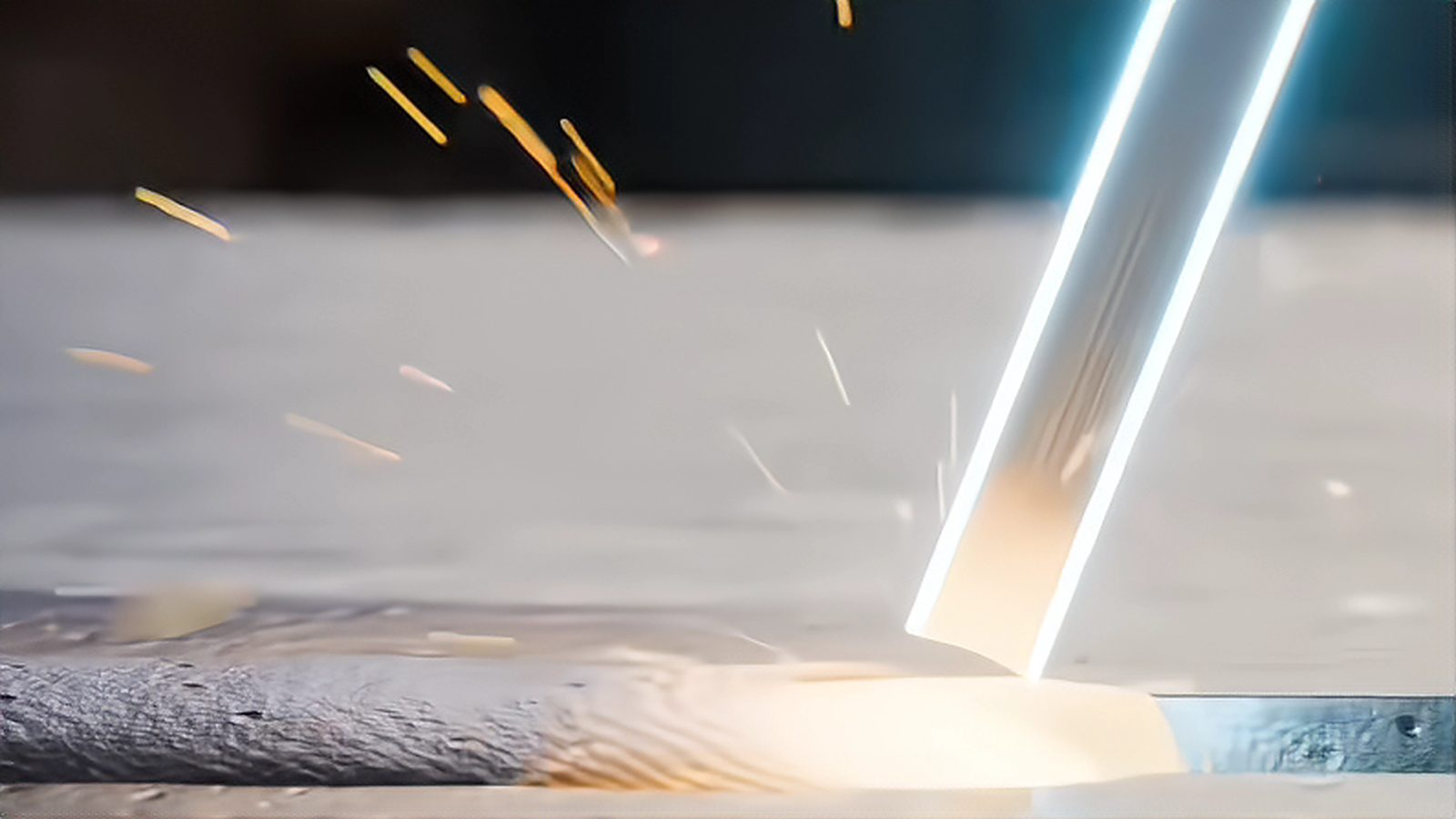
On a laser welding setup sheet, power is the number everyone reads first, but power alone says little about what happens at the joint. What governs melting is power density, the power delivered per unit area, and spot size is what converts one into the other. Change the spot diameter and you change the process. This article covers how focus position sets the working regime and how the standards define spot size. The overview of laser welding parameters is a useful companion.
Power Alone Does Not Weld
A ten-kilowatt source focused to a large spot and the same source focused to a small spot are two different tools. The relationship is geometric: for a given power, halving the spot diameter concentrates the same energy into roughly a quarter of the area, so power density rises by about four times. Two machines with identical ratings can therefore behave completely differently on the same part. Record the spot size, or the optic combination that produces it, next to the power and speed.
How Spot Size and Power Density Relate
Spot size is best understood as a distribution rather than a hard edge, because the beam has a peak in the centre and falls away toward the edges. Standards therefore measure a width that contains a defined fraction of the energy rather than a visible boundary. ISO 11146-1:2021 covers test methods for beam widths, divergence angles and beam propagation ratios for stigmatic and simple astigmatic beams, and ISO 11146-2:2021 extends the same methods to general astigmatic beams.
The Two Process Regimes
At low power density the beam mainly heats the surface and the melt flows by conduction, producing a wide, shallow weld. Above a threshold that depends on material and wavelength, the surface vaporises, a keyhole opens, and the beam is absorbed down the depth of that vapour channel, so penetration jumps and the weld becomes narrow and deep. For many metals on a fibre laser the transition sits on the order of a megawatt per square centimetre, but treat that as a typical order of magnitude rather than a fixed number.
How Focus Position Changes the Spot
Focus position sets the spot size, and defocus is simply a way of trading intensity for coverage, because moving the part above or below the focal plane makes the beam expand. Beam parameter product and fibre core diameter decide how small the spot can be and how quickly it grows away from focus, so changing the fibre, collimator or focusing lens rewrites the relationship. A small spot has a short depth of focus, so it stays tight over only a narrow range of part position, while a larger spot tolerates more variation in stand-off.
Measuring Spot Size the Standard Way
Proper measurement follows the beam rather than a single sample point. ISO 11146-1:2021 describes how to characterise beam width and propagation, which in practice means mapping the beam through focus to find the waist and its position, an approach usually called a caustic measurement. ISO 13694:2026 covers test methods for the beam irradiance distribution, that is, how the energy is spread across the spot, and it replaced the earlier 2018 edition along with a change of title. Burn paper is useful for spotting drift but reads larger than the true beam.
Beam Quality and Why Optics Change Everything
Two lasers with the same output power can deliver very different power density because beam quality differs. A source with a low beam parameter product can be focused to a smaller spot at the same working distance, which is what makes single-mode sources attractive for thin, precise work. Multi-mode sources with a larger beam parameter product settle for a bigger spot but tolerate more misalignment and deliver a broader weld. ISO 11554:2025 addresses test methods for beam power, energy and temporal characteristics.
Thin Sheet Punishes a Small Spot
Sensitivity to spot size depends strongly on thickness. On thin sheet, a tight spot with high power density can cross the keyhole threshold and burn through almost instantly. On thick sections the pressure is reversed, because you need enough power density to establish and hold a keyhole at the required depth, and a spot that is too large cannot reach it. Choose the spot from the thickness and joint type first, then set power and speed inside the window it allows.
Matching Spot to Material and Joint
Highly reflective materials such as copper and aluminium ask more of the beam, because much of the energy is reflected until the keyhole is established, so a higher power density is usually needed to start and keep a stable melt. Where you use beam oscillation, the spot that matters is the effective one swept across the joint, and the wobble welding approach changes how that energy is distributed. On a scanning system the deliverable spot grows with distance from the centre of the field. The comparison of galvo scanners and gantry motion covers the mechanical side.
Practical Focus Optimisation and Common Mistakes
Treat focus as an experimental variable and work a small matrix: hold power and speed, step the focus position in known increments around the expected optimum, and judge by weld cross-section rather than by sound alone. Operators raise power to compensate for a defocus that should have been corrected, and forget that a contaminated cover glass both absorbs energy and distorts the beam. Any of those turns a stable process into a drifting one that appears first as welding defects rather than as a change in the numbers. Record the optic stack and the measured spot on the procedure specification, since ISO 15609-4:2009 deals with laser beam welding.
If you take one habit from this, manage focus position as a first-class parameter, not as a correction you apply when something goes wrong. Record the optic stack, verify the focus on a schedule, and check the cover glass before you blame the program. Ask which definition of spot size a number refers to, and measure the beam with a recognised method rather than trusting a label. More background sits in the welding parameters section of the site.
Sources and references
- ISO 11146-1:2021 Lasers and laser-related equipment - Test methods for laser beam widths, divergence angles and beam propagation ratios - Part 1: Stigmatic and simple astigmatic beams - test methods for beam width and propagation View source
- ISO 11146-2:2021 Lasers and laser-related equipment - Test methods for laser beam widths, divergence angles and beam propagation ratios - Part 2: General astigmatic beams - extends the beam width methods to general astigmatic beams View source
- ISO 13694:2026 Optics and photonics - Lasers and laser-related equipment - Test methods for laser beam irradiance (fluence) distribution - the current edition for measuring how energy is spread across the spot View source
- ISO 11554:2025 Lasers and laser-related equipment - Test methods for laser beam power, energy and temporal characteristics - test methods for beam power, energy and time-dependent behaviour View source
- ISO 15609-4:2009 Specification and qualification of welding procedures - Welding procedure specification - Part 4: Laser beam welding - the procedure specification part specific to laser beam welding View source
Comments (0)
No comments yet.
Sign in to join the discussion.