Fiber Laser Welding Parameters Explained: Power, Speed and Focus Offset
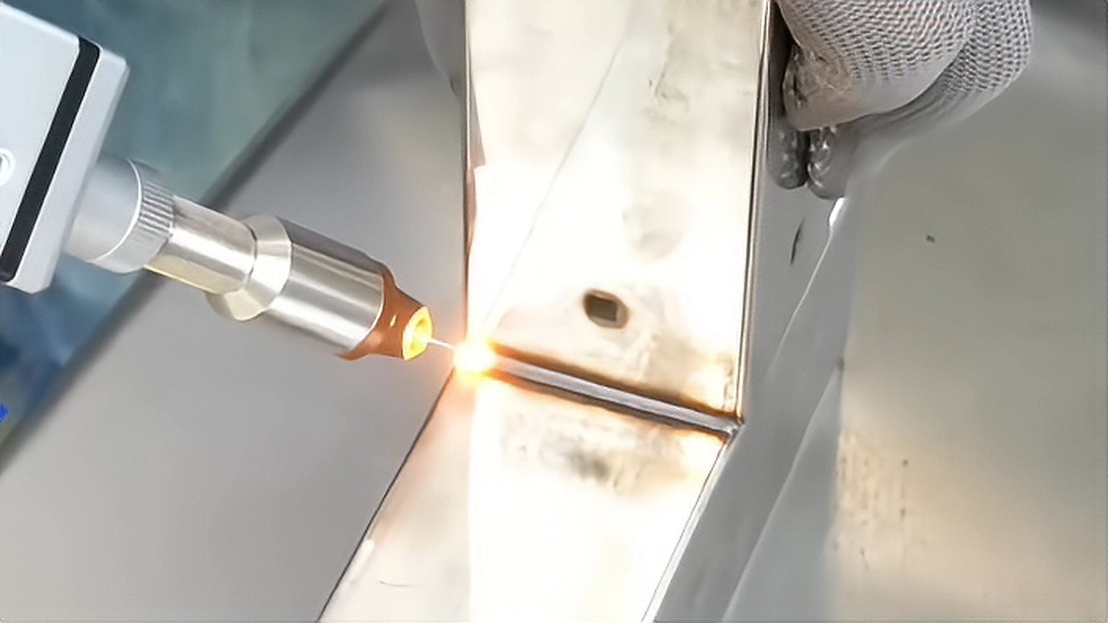
Fiber laser welding parameters decide whether a joint is sound long before any robot motion is programmed, and the three that matter most are laser power, travel speed and focus offset. This article explains how those three variables pull against each other, gives the starting ranges that are common in industry, and lays out an adjustment order that lets you qualify a new job on a handful of coupons instead of a full shift of guessing.
Energy Density Is the Variable Behind the Variables
Power, speed and spot size never act alone. What the melt pool actually sees is energy density, meaning the delivered power spread over the spot area and multiplied by the time the beam spends on a given point. A 2 kW beam focused to a 0.2 mm spot and moved at walking pace produces a very different weld from the same beam defocused to 0.6 mm and moved three times faster. When a weld runs too hot, the cure is not automatically less power, because speed and focus change the same balance.
That is why experienced programmers treat the three settings as one group. Moving the focus offset alone changes the spot diameter, which changes energy density, which in turn changes the speed at which the keyhole remains stable. An adjustment plan that moves one knob without watching the other two tends to chase its own tail.
Power Sets the Ceiling on Penetration
For 1 mm stainless steel or mild steel, 1 to 2 kW is a common starting range, and foils below 0.3 mm weld comfortably under 1 kW. At 3 mm, most production cells run between 2 and 4 kW, while 6 mm and thicker generally needs 6 kW and above together with a larger spot to keep the keyhole steady. These figures describe normal industry practice rather than measured results, and the machine, the optics and the shielding gas all shift them.
Raise power only when you need more penetration or more speed to hit cycle time. Extra power at unchanged speed deepens the keyhole, but it also widens the heat affected zone and raises the risk of spatter and root drop out. On thin sheet, surplus power usually shows up as a rough crown and a darker oxide band rather than as a better weld.
Travel Speed Controls Keyhole Stability and Cycle Time
Speed governs productivity more directly than any other setting, and it is also the setting that most often pushes a process out of its window. As a general rule, doubling speed at constant power gives a shallower and narrower weld. When speed climbs too high for the available power, the keyhole can no longer follow the beam, and the result is intermittent penetration, humping or a chain of holes along the seam.
Typical production speeds for steel at moderate thickness fall between 1 and 6 meters per minute, with considerably higher values on thin material and slower values when a wide spot is used for gap tolerance. Read the weld cap rather than the display. A smooth, evenly rippled crown points to a stable keyhole, while a bright unstable plume with heavy spatter usually means that speed and power no longer match.
Focus Offset Tunes Spot Size and Weld Profile
Focus offset, the distance between the beam waist and the workpiece surface, is the most underrated of the three settings because it is easy to leave at zero. Placing the waist slightly above the surface widens the spot and produces a wider, shallower weld closer to conduction mode. Placing the waist a little below the surface concentrates energy deeper into the material and favors penetration with a narrow, nearly parallel sided seam.
On 1 mm steel, offsets within roughly 1 mm of the surface are already enough to change the weld shape noticeably. Thicker sections often run with the waist a few millimeters below the surface, which also makes the process far less sensitive to small variations in part height. If penetration changes when the fixture clamps differently, the focus position is doing too much of the work.
A Fixed Sequence for a New Job
Begin with the focus position recommended by the optics supplier for that material thickness, and set power at a value typical for the thickness. Raise speed until penetration just starts to become intermittent, then back off by roughly 15 to 20 percent to leave margin for normal variation in the joint. Next, refine power in steps of 5 to 10 percent to clean up spatter and undercut. Only after that should you adjust focus offset to fine tune the seam profile.
Keep one coupon per condition and label each one with its parameter set, because a weld that looks acceptable on the bench may already sit at the edge of the window. Record the width of the heat affected zone, the amount of spatter and the shape of the cap every time. A couple of hours of disciplined trials usually produces a recipe you can trust, while scattered adjustments across many parts usually produce scrap.
Pick the thickness you weld most often, prepare five identical coupons, and run the sequence above once with focus fixed and once with two different offset values. The notes from those coupons will transfer to other jobs far more reliably than any published table. Once the recipe holds, lock the values into the program and treat any later change as an engineering change that requires a fresh coupon.
Comments (0)
No comments yet.
Sign in to join the discussion.