Penetration in Laser Welding: Setting Depth of Fusion by Thickness
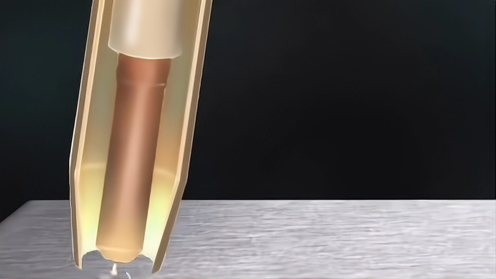
Penetration is the result every laser welding program is judged on, yet it is not a value you can dial in directly. Depth of fusion is the outcome of power, travel speed, spot size and the material's response. The engineering problem is how to find a stable curve for a given thickness and hold it in production. It comes down to the mechanics behind penetration and to proving depth with evidence. The general laser welding parameters overview is a helpful companion.
Penetration Is a Result, Not a Setting
Raising power and lowering speed both increase penetration, but at different costs. More power widens the keyhole and raises total heat input, while lower speed gives the material more time to absorb heat. That is why two parameter sets reaching the same depth are not interchangeable: one may run hot and wide with a coarser grain structure, the other tight and narrow with a different defect profile. Consistency across a seam matters as much as the average depth.
What Full Penetration Means in a Specification
Partial and full penetration are not just different depths; they are different acceptance regimes. A partial-penetration weld is judged on whether the fused depth reaches a required value, while a full-penetration weld is judged on whether the root is fully fused. ISO 13919-1:2019 sets quality levels B, C and D for electron and laser-beam welded joints in steel, nickel, titanium and their alloys, and ISO 13919-2:2021 does the same for aluminium, magnesium and their alloys and pure copper.
Single-Pass Limits by Thickness
Single-pass penetration is comfortable through thin and medium sections and becomes harder as thickness grows. As sections get thicker, the power density needed to hold a keyhole to depth rises and the keyhole becomes less stable, so single-pass welding is typically practical only up to a limited depth. A published example shows the scale involved: TWI reported that a 9 kW Nd:YAG facility achieved full penetration in C-Mn steel at around 12 mm at roughly 0.7 m per minute, and at about 15 mm at roughly 0.35 m per minute, with a maximum near 18 mm in that work. Treat those as one facility's results rather than a general promise.
Speed, Power and the Penetration Curve
The most useful tool on the shop floor is a penetration-versus-speed curve for the material and thickness you actually run. Fix power and optics, vary speed, and record depth, width and defects; a second power level gives you a map of the working window. Change one variable in small steps, on the order of 10 to 20 percent, and re-check before moving on, because the response is rarely linear near the edges of the window.
Focus Position and Penetration
Focus position shifts penetration without changing any number on the power supply. Placing the focal point at the surface, slightly below it or above it changes the effective spot size and the depth of peak intensity. Depth of focus also matters, because a short focus demands tighter control of part position. A contaminated cover glass acts like a slow defocus, so an unexplained drift in penetration is usually an optics problem.
Depth, Width and Keyhole Stability
A deep, narrow weld looks impressive on a cross-section, but a large ratio of depth to width is not a virtue in itself. As the keyhole gets deeper relative to its width, it becomes more prone to collapse and to root irregularities, which raises the risk of common welding defects. A modestly wider bead usually costs a little more heat but buys a more stable process.
Multi-Pass, Filler and Thick Sections
When a single pass cannot reach the required depth, the answer is usually more passes, a gap, or filler. Multi-pass welding with a narrow gap adds material in stages and builds thick sections without demanding one enormous keyhole. AWS C7.4/C7.4M:2017-AMD1 addresses process specification and operator qualification for laser beam welding.
Why Thick Sections Change the Physics
Thick material changes more than the numbers; it changes the physics around the keyhole. A deeper keyhole produces more vapour and a stronger plume that can scatter or absorb the beam, and the molten pool grows heavier and harder to support, so spatter, humping and undercut become more likely. When a thick-section process behaves erratically, inspect gas flow, nozzle stand-off and plume control before rewriting power and speed.
How the Standards Treat Procedures and Acceptance
Standards separate three questions that are easy to blur: what quality level the part must meet, how the weld is to be tested, and what counts as acceptable. ISO 15614-11:2025 describes how electron and laser beam welding procedures are qualified, and ISO 17635:2025 gives general rules for choosing non-destructive testing methods. A qualified procedure is not the same as a passed part, so keep the three documents consistent.
Measuring Penetration and Keeping Records
No amount of experience replaces a section when the question is how deep the weld actually went. Cut representative samples, polish and etch them, and measure penetration and width at agreed locations. Where a section is not practical, radiographic or ultrasonic methods may be used, but their suitability depends on thickness and material and should follow the method-selection rules. Write the acceptance depth and sectioning into the laser welding cell specification.
Set penetration the way you would set any other result: thickness first, then target depth, then the profile you are willing to accept, then the parameter window that delivers it within tolerance. Verify with a section, write the numbers down, and keep the evidence with the procedure. Work in that order and penetration becomes a characteristic you control rather than a number you chase. More on these relationships sits in the welding parameters section.
Sources and references
- TWI Materials Processing with a 10kW Nd:YAG Laser Facility (1999) - reports full penetration in C-Mn steel at around 12 mm at roughly 0.7 m per minute, about 15 mm at roughly 0.35 m per minute and a maximum near 18 mm View source
- AWS C7.4/C7.4M:2017-AMD1 Process Specification and Operator Qualification for Laser Beam Welding - the process specification and operator qualification framework for laser beam welding View source
- ISO 13919-1:2019 Electron and laser-beam welded joints - Quality levels for imperfections - Part 1: Steel, nickel, titanium and their alloys - defines quality levels B, C and D for laser and electron beam welds View source
- ISO 13919-2:2021 Electron and laser-beam welded joints - Quality levels for imperfections - Part 2: Aluminium, magnesium and their alloys and pure copper - defines the equivalent quality levels for aluminium, magnesium and copper View source
- ISO 15614-11:2025 Specification and qualification of welding procedures - Welding procedure test - Part 11: Electron and laser beam welding - how laser and electron beam welding procedures are qualified View source
- ISO 17635:2025 Non-destructive testing of welds - General rules for metallic materials - general rules for choosing non-destructive testing methods for welds View source
Comments (0)
No comments yet.
Sign in to join the discussion.