Offline Programming vs Teach Pendant for Laser Robots
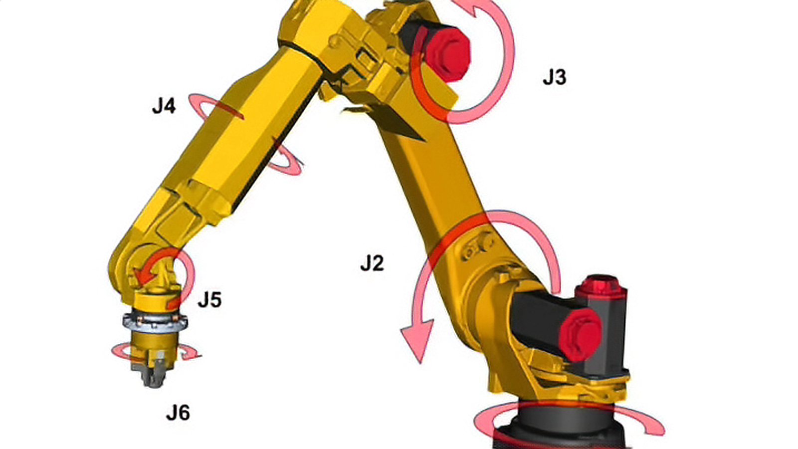
Offline programming laser robot work moves path creation off the shop floor and into a software model, while a teach pendant keeps it in front of the machine. The choice matters most in high mix, low volume production, where the hours spent proving a path can exceed the hours spent welding. The decision also sits closer to the physics of laser welding than most general robot programming advice admits, because the energy spot is small, the alignment window is narrow, and the geometry that defines the path is the beam rather than a contact tip. This article compares the two methods on the points that actually decide the outcome for laser work: what each method is good at, how much machine time programming consumes, how repeatable and how accurate the robot really is, what has to be calibrated before an offline path will run, and how much of the effort survives the next product change.
Two ways to build the same path
With a pendant, an operator jogs the robot to each point, records the position, sets the orientation, and links the points into a path. The model in the controller is the part itself, so any mismatch between CAD and reality never enters the conversation. With offline programming, the path is created from CAD data in a simulation environment, checked for reach and collision, and then post processed into controller code that is downloaded to the robot. The geometry comes from the model, which means the accuracy of the finished path depends on how well the cell model matches the real cell. Modern offline programming environments read common CAD exchange formats and treat the cell as a digital twin, so the path can be validated against the real fixture, the real torch and the real robot envelope before the machine is touched.
What offline programming actually checks
The value of the simulation is not that it draws a path, but that it answers questions the shop floor cannot answer cheaply. A published engineering case from TWI modelled the cell, the robot, the workpiece and the fibre delivery in simulation software and ran kinematic simulation on it to assess accessibility, working envelope and robot to component collision, and to decide the welding sequence and the best position of the component relative to the robot. That is the real deliverable of offline programming: the sequence, the approach moves, the safe heights and the part position, all settled before a single weld is made. Collision and singularity checks fall out of the same model. What such studies do not replace is proving the process on a real part, because the simulation validates the motion, not the metallurgy.
Where the teach pendant still wins
For a single part, a repair, or a prototype with no reliable CAD, teaching by hand is usually faster than building a model and calibrating it. The pendant is also the right tool when the seam exists only as a physical feature, for example an edge produced by a casting or a hand formed joint, because the operator can follow the feature directly. Laser specific tasks favor it too. Setting the tool center point, verifying that the focal position sits on the surface, and trimming a path so the beam clears a clamp are all quick on the pendant after the path exists. The penalty is that the machine is occupied while this happens, and a hot, fume filled cell makes the work slow and unpleasant. There is a useful counterexample worth knowing: in one three dimensional robotic laser welding development programme reported by TWI, every weld was taught manually, first using a mechanical pointer mounted on the welding head and later a laser diode pointer, and the simulation software was not used to program the robot at all. The simulation was used for layout and reach studies instead. That is a fair picture of how the two tools divide the work in real projects.
Repeatability is not accuracy
The single most important fact behind offline programming is that industrial robots are repeatable but not accurate. Repeatability is the ability to return to a point that has already been taught; absolute accuracy is the ability to move to a coordinate the robot has never visited. These are different quantities and the gap between them is large. A published measurement on a six axis industrial robot recorded absolute positioning accuracy of about 50 micrometres against a repeatability of about 20 micrometres, so the robot could return to a taught point far more precisely than it could reach a commanded one. ISO 9283, Manipulating industrial robots, Performance criteria and related test methods, is the reference that defines how these performance criteria are described and tested; the current published edition is the second edition from 1998, which replaced the 1990 edition and its 1991 amendment, and it is now administered under ISO/TC 299. The practical consequence is simple: a path generated from a model and downloaded to the controller is executed by a machine whose own positioning error is larger than the tolerance the laser process cares about.
The calibration chain you cannot skip
Every offline program inherits the error between the model and the real cell. That error is corrected in one of three ways: calibrating the robot against a measuring device such as a laser tracker, measuring the fixture and the part with touch sensing at the start of each cycle, or letting a seam tracking sensor correct the path while welding. The third option is the most common in laser cells because it also absorbs part to part variation, but it works only if the offline path is already close enough for the sensor to find the joint. Tool center point calibration deserves separate attention because in laser welding the tool center point is the beam focus. A research programme on seam tracking for robotic laser welding reported a calibration method that held tool center point accuracy to roughly 70 micrometres where the process required 100 micrometres, which shows both that the target is achievable and that it is measured in tens of micrometres rather than millimetres. The same work reported that the taught points and the calibrated frame were held to a similar order. The honest conclusion from the published engineering literature is that offline programming for laser welding is a calibration programme with a programming tool attached, not the other way round. TWI states the requirement plainly: for offline programming to succeed, the model must match the real workpiece, work area and equipment, and time must be allocated for calibration.
Laser work is less forgiving of alignment
Laser welding raises the stakes on alignment because the energy spot is small. TWI describes the laser spot as generally under one millimetre in diameter and notes that the beam must be aligned accurately with the joint, since misalignment produces lack of penetration or lack of fusion rather than a visible cosmetic defect. Joint type changes how much tolerance you get. A square butt joint demands the most exact alignment of the common configurations, while a stake weld tolerates the most. Speed matters as well, because laser welding generally runs faster than many other processes and the robot has to hold its alignment dynamically while moving rather than only when parked. For anyone specifying a cell, this is the reason a laser welding robot is judged on dynamic performance and not only on the static accuracy printed in a datasheet. Part quality feeds into the same equation: parts should be machined to tight tolerance, their position and orientation relative to the robot must be accurate and repeatable, and because thermal cycling moves metal during welding, tacking or clamping is needed to hold the assembly while the path runs. Fixture repeatability and thermal growth set the floor on achievable accuracy regardless of how the path was created.
When the process stops being axially symmetric
There is a subtlety in laser welding that catches people out when they move from a welding torch to a laser head. Basic laser welding is axially symmetric about the beam axis, so rotating the head around that axis changes nothing and the robot has unusual freedom to choose a comfortable configuration. Add a filler wire nozzle or a plasma control nozzle and the symmetry disappears. The tool center point stops being a point and becomes a vector with a required direction, the process becomes direction specific, and the robot can no longer take any convenient posture it likes. On joints that vary in three dimensions, such as saddle joints on a pipe, that constraint becomes significant and is often what forces an extra axis of motion or a positioner into the cell. For offline programming this matters twice over, because the post processor and the tool model must represent that direction requirement, and a program that looks collision free in simulation can still put the wire nozzle on the wrong side of the seam.
Seam tracking changes the requirement
Seam tracking is often presented as the answer to offline programming error, and it is, within limits. TWI has demonstrated adaptive control with laser vision sensing that tracked a butt joint in real time on a seven axis robot and adjusted robot position and travel speed according to the joint fit up. A recent conference paper on requirements for robust seam tracking in robotic laser welding puts the positioning requirement at sub millimetre level, with the joint type and plate thickness setting how tight it has to be, and notes that detecting and correcting deviation requires resolution at micrometre level. The practical reading is that a tracking sensor can absorb variation and small model error, but it needs a path that is already in the right neighbourhood. Treating sensing as a substitute for calibration rather than a correction layer on top of it is a common and expensive mistake.
What the standards do and do not tell you
Several standards frame this work, and their current editions are worth stating precisely because the versions changed recently. ISO 10218-1:2025, Robotics, Safety requirements, Part 1, Industrial robots, is the third edition and replaces the 2011 version. ISO 10218-2:2025 covers industrial robot applications and robot cells, replaces its 2011 counterpart, and now incorporates the collaborative application requirements that previously sat in ISO/TS 15066. That technical specification, ISO/TS 15066:2016 on collaborative robots, is still published but its content has largely moved into Part 2 and it is marked for revision. For laser equipment specifically, ISO 11553-1:2020, Safety of machinery, Laser processing machines, Part 1, Laser safety requirements, is the second edition and replaced the 2005 version. What none of these documents will give you is a table of programming tolerances for focus offset, standoff distance, laser on and off timing, dwell or gas sequencing for a robot cell. Those figures circulate in supplier documentation and training material, but we could not find them published by a standards body or an independent research institute in a form that can be cited, so this article does not quote any. If a supplier asserts a tolerance, ask what it was measured on and against which reference. The safety requirements that surround the cell are a separate question from the programming tolerances, and we cover them in our laser welding safety overview.
A practical split for high mix production
Most shops that run many short batches settle on a division of labor rather than a pure choice. The base path is created offline and includes approach points, safe heights and a complete welding sequence, then the first article is touched up on the pendant and the corrected positions are written back into the offline model so the next run starts from the improved version. Parent programs that read part offsets from a table let one proven path serve several variants without regeneration. For a family with stable CAD and repeatable fixturing, offline programming is the better investment, and for one off fabrication the pendant remains the fastest route to a sound weld. If you are still writing the requirement rather than the program, the points that decide whether offline programming will ever pay off are set out in our laser welding cell specification checklist. The deciding question is not which method is more modern but how much of the programming effort will still be usable on the next job.
Sources and references
- ISO 9283:1998 Manipulating industrial robots, Performance criteria and related test methods, second edition replacing the 1990 edition and its 1991 amendment, administered under ISO/TC 299 View source
- ISO 10218-1:2025 Robotics, Safety requirements, Part 1, Industrial robots, third edition replacing the 2011 version View source
- ISO 10218-2:2025 Robotics, Safety requirements, Part 2, Industrial robot applications and robot cells, incorporating the former ISO/TS 15066 collaborative requirements View source
- ISO/TS 15066:2016 Robots and robotic devices, Collaborative robots, still published but marked for revision View source
- ISO 11553-1:2020 Safety of machinery, Laser processing machines, Part 1, Laser safety requirements, second edition replacing the 2005 version View source
- TWI Three-Dimensional Robotic High-Power Nd:YAG Laser Welding, Opportunities and Obstacles, describes the sub-millimetre laser spot, the alignment demand of square butt versus stake welds, the loss of axial symmetry when filler or plasma nozzles are added, part and fixture requirements, the manual teaching used on the project, and the statement that offline programming needs an exact model plus allocated calibration time View source
- TWI Adaptive Control Hybrid Welding with a High Brightness Laser, laser vision sensing tracking a butt joint in real time with adjustment of robot position and travel speed View source
- University of Twente, Seam tracking for laser welding with an industrial robot, gives the measured absolute accuracy of about 50 micrometres against repeatability of about 20 micrometres, and the tool center point calibration held to roughly 70 micrometres against a 100 micrometre requirement View source
- LiM 2025 conference proceedings, Definition of requirements for robust seam-tracking in robotic laser welding applications, states the sub-millimetre positioning requirement and the micrometre level resolution needed to detect and correct deviation View source
Comments (0)
No comments yet.
Sign in to join the discussion.