Cobot Laser Welding: What It Can and Cannot Do Safely
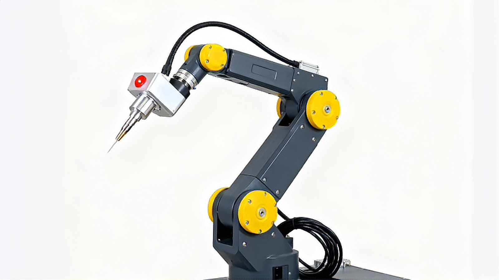
Cobot laser welding is often presented as a way to bring a laser head to a workpiece without paying for a full enclosure, and that claim breaks down the first time somebody measures the beam instead of estimating it. A collaborative arm is designed and certified against mechanical contact criteria, while the radiation it carries is governed by a completely separate set of rules. This article keeps the two hazard families apart, shows the power and duty range where a cobot is a sound engineering choice, and lists the checks that decide whether a cell can be released to production.
The Arm and the Beam Follow Different Rules
Part 1 of ISO 10218 sets the safety requirements for the robot itself, and the collaborative modes originally described in ISO/TS 15066 are now largely folded into part 2 (https://www.iso.org/standard/73933.html). Everything in that family of documents addresses mechanical hazards, which are clamping, crushing, impact and trapping. The laser is a different problem.
Part 1 of IEC 60825 defines the classification of laser products and the measurement conditions behind it, and a welding source of several hundred watts or more normally lands in Class 4, which means the beam stays dangerous even after a diffuse reflection (https://webstore.iec.ch/en/publication/3587). The requirements for guards and interlocked enclosures are developed further in part 4 of the same standard (https://webstore.iec.ch/en/publication/30245). The practical consequence is blunt. Slowing an arm to 250 mm per second and limiting its contact force changes nothing about the accessible emission. A compliant arm carrying a kilowatt of near infrared light is a Class 4 laser installation, and the paperwork that proves the arm is safe to touch says nothing about the eye.
Where a Cobot Earns Its Place
Cobot welding is at its best on thin material, short seams and parts that change often. Integrators working in this area commonly stay in the few hundred watt range and accept a modest duty cycle, welding sheet from roughly 0.5 mm to 2 mm in lap, fillet or corner joints. That is common industry practice rather than a hard technical limit.
Stiffness matters more than the payload figure. A collaborative arm is deliberately compliant, so acceleration during a direction change produces a small deflection at the wrist, and the focal spot moves with it. Depth of focus on a typical welding optic is measured in a few tenths of a millimeter, so a deflection of that order changes penetration on a given sample. Before trusting a cobot on a real seam, run the delivered head, slide and cable package at the intended acceleration and measure the deviation at the work plane. Collision sensitivity needs the same treatment, because a heavy head with a bulky shroud raises the effective threshold and can hide a light contact verified on a bare flange.
Where the Cobot Stops Being the Right Answer
A cobot is a poor match for thick sections, long straight seams at high travel speed, heavy duty cycles and reflective materials that need power for a stable keyhole. The failure is rarely dramatic. It appears as drift over a shift, as a focal position that moves once the head is warm, and as cable and shroud wear that accumulates faster than on a rigid machine. When the process window needs more than a narrow band of power and speed, the compliance of the arm becomes a variable the process cannot absorb, and a gantry or a rigid six axis robot usually costs less over the life of the cell.
Design the Shared Zone Around the Beam, Not the Arm
There are two workable arrangements. The first is a light tight enclosure with the part entering through a light tight door or a transfer tunnel, which keeps the process zone inaccessible while the beam is enabled. The second is a closed welding head in which the beam is contained inside a shroud that rests on the part, so no free space beam path exists during the weld. A free space beam crossing an area where a person can reach is not a defensible design at welding power levels.
Interlocks have to terminate emission rather than pause the program, which means the shutter closes and the source ramps down, and the response time must be measured and written into the access rules. Speed and separation monitoring and protective stop functions can keep people away from the process zone, but the boundary they protect has to be the enclosure, not the reach envelope of the arm. Fume extraction also changes when a person stands close to the head, so capture at the nozzle beats a general ventilation upgrade. Eyewear remains a secondary control for alignment and service, and it has to be specified for the working wavelength.
Verify Before You Release the Cell
Ask for four documents before acceptance, which are the classification and wavelength statement, the guard and window specification with optical density values, the interlock and shutter timing data, and the collision sensitivity results with the delivered tooling. Then run a leakage test at full power with the worst head orientation, the doors closed and a detector placed at every entry point, including cable pass throughs and the gap where the arm passes the guard. Confirm that alignment runs at reduced power under a key switch, that the monitored stop has been validated with the beam enabled, and that the risk assessment carries the signature of both the laser safety officer and the person responsible for robot safety.
Treat every cobot laser project as two projects that happen to share a floor. Write the mechanical case and the optical case as separate documents, give one engineer responsibility for each, and do not release the cell until the leakage test and the shutter timing are recorded in the same file as the robot validation. That habit costs a day at the start and prevents the argument that stops a line six months later.
Comments (0)
No comments yet.
Sign in to join the discussion.