Laser Cleaning Robots: Removing Rust, Paint and Coatings
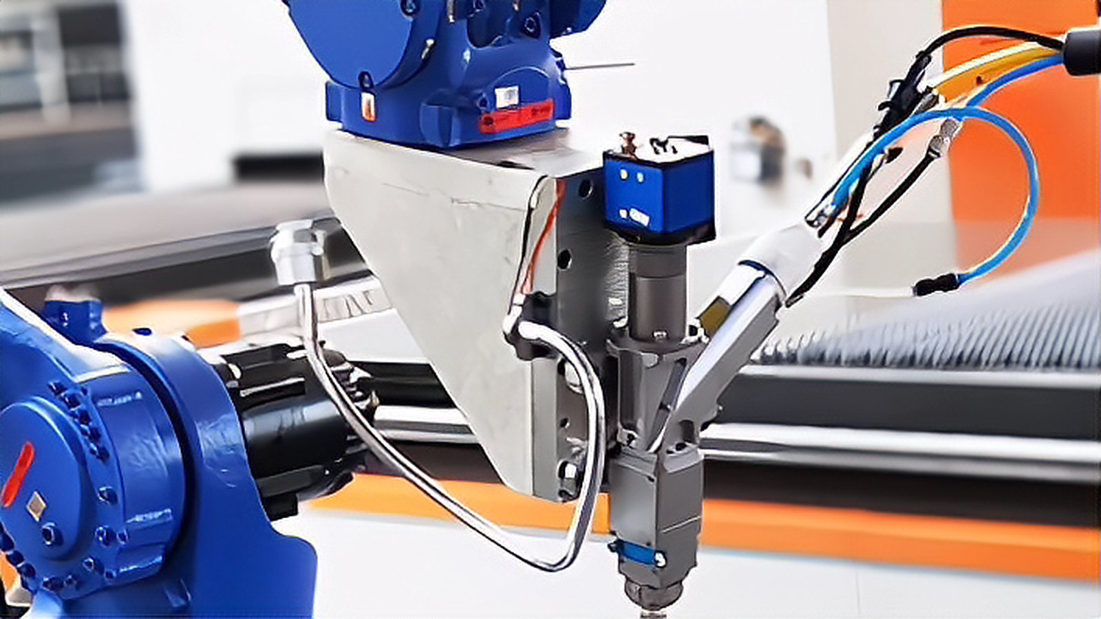
A laser cleaning robot removes a surface layer with light instead of grit, chemicals or a scraper, and that difference changes both the quality argument and the integration problem. Rust, mill scale, oxide, oil, primer and paint can all be taken off a metal surface with a pulsed beam and no abrasive media, which means no blasting grit to buy, contain and dispose of. The same property makes the process unforgiving: the window between cleaning and damaging the surface can be narrow, and on thin material the mistake shows up as a discolored or warped part rather than as a hole. This article covers how to set the power density, where substrate damage comes from and what a robot cell around the process has to include.
How Ablation Removes a Layer
The mechanism is ablation rather than melting. A short pulse delivers its energy before the heat can spread far into the metal below, so the contaminant layer is ejected as vapor and fine particles while the average temperature of the part stays low. That is why a laser can strip a coating from a thin panel without the distortion a torch or a grinding disc would cause. It is also why the process works layer by layer: a thick coating is removed in several passes, each tuned for the layer it is meeting rather than for the finished result.
Choosing Power Density and Pulse Settings
Average power, pulse energy, pulse duration, repetition rate and spot size together set the power density at the surface, and power density is the parameter that decides what happens. Industrial cleaning heads commonly run average powers from around 100 W to about 1 kW, pulse energies of roughly 0.5 mJ to 10 mJ, pulse durations from tens to a few hundred nanoseconds and repetition rates from about 20 kHz to 500 kHz, with spot sizes of roughly 0.5 mm to 5 mm. A useful way to think about the settings is in terms of thresholds: the coating has a level of energy per unit area at which it starts to come off, and the substrate has a higher level at which it begins to be damaged. The process window is the gap between those two thresholds, and it exists only while the pulse is short enough that heat does not build up in the base metal.
Protecting the Substrate
Damage usually comes from accumulated heat rather than from a single aggressive pulse. A high repetition rate with a slow scan and heavy overlap keeps pouring energy into the same area, and the part either oxidizes, tempers, warps or takes on a polished look as the surface melts and reflows. Thin sheet, spring steel and anodized aluminum are the cases that fail first, and on galvanized steel the zinc layer itself can be removed, which changes corrosion behavior even when the surface looks clean. The practical controls are to spread the scan so dwell time per unit area drops, to reduce repetition rate or pulse energy, to pause on thin parts, and to keep the head moving, since a stationary beam damages almost anything within a fraction of a second. It also helps to know what the coating contains before you start. Old paint can carry lead, chromium or other heavy metals, and the removed material has to be captured and handled as the local rules require rather than left to settle on the floor.
Safety and Cell Integration
Cleaning heads are usually Class 4 laser products, so the cell needs the same treatment as a welding or cutting cell: an enclosure or a screened area, interlocks that stop emission when a door or curtain opens, a beam path that is blocked or enclosed, and eye protection matched to the wavelength and the energy for anyone inside the boundary. OSHA addresses laser hazards through its general industry standards and publishes a topic page for hazard recognition and controls, which is a reasonable starting point for the risk assessment (https://www.osha.gov/laser-hazards). Fume and dust extraction belongs at the head, with the nozzle close to the spot, because ablated coatings become airborne particles and the visible plume is not a reliable measure of what is released. Standoff distance also has to be held, since the process window is narrow in the direction of the surface, so an optical standoff sensor, a mechanical follower or a floating head is usually part of the design. The parts must also be presented repeatably, because a robot that cleans a curved surface at a constant programmed speed but a varying angle will leave stripes.
Setting the Process Window on Real Parts
Never quote an area rate without the layer it applies to. Cleaning speed depends on the coating chemistry, its thickness and how well it absorbs the wavelength, so the same head may strip light rust quickly and creep across a thick elastomeric coating. Start with a scrap panel of the real material and the real coating, sweep power and scan speed in a small grid, and judge the result with a consistent method such as a visual standard, a tape test or a handheld color measurement rather than by eye at the end of a shift. Record where the surface begins to discolor, because that point marks the edge of the window, and then run production with a margin inside it.
Document that window for every coating on the job list before the cleaning step is automated. Put the settings, the standoff tolerance, the extraction requirement and the inspection method into the work instruction, and recheck the window whenever a new coating or material appears. A robot that repeats a verified recipe all shift is worth more than one that cleans faster only on commissioning day.
Comments (0)
No comments yet.
Sign in to join the discussion.