CO2 Laser Cutting: A Practical Guide for Robot Cells
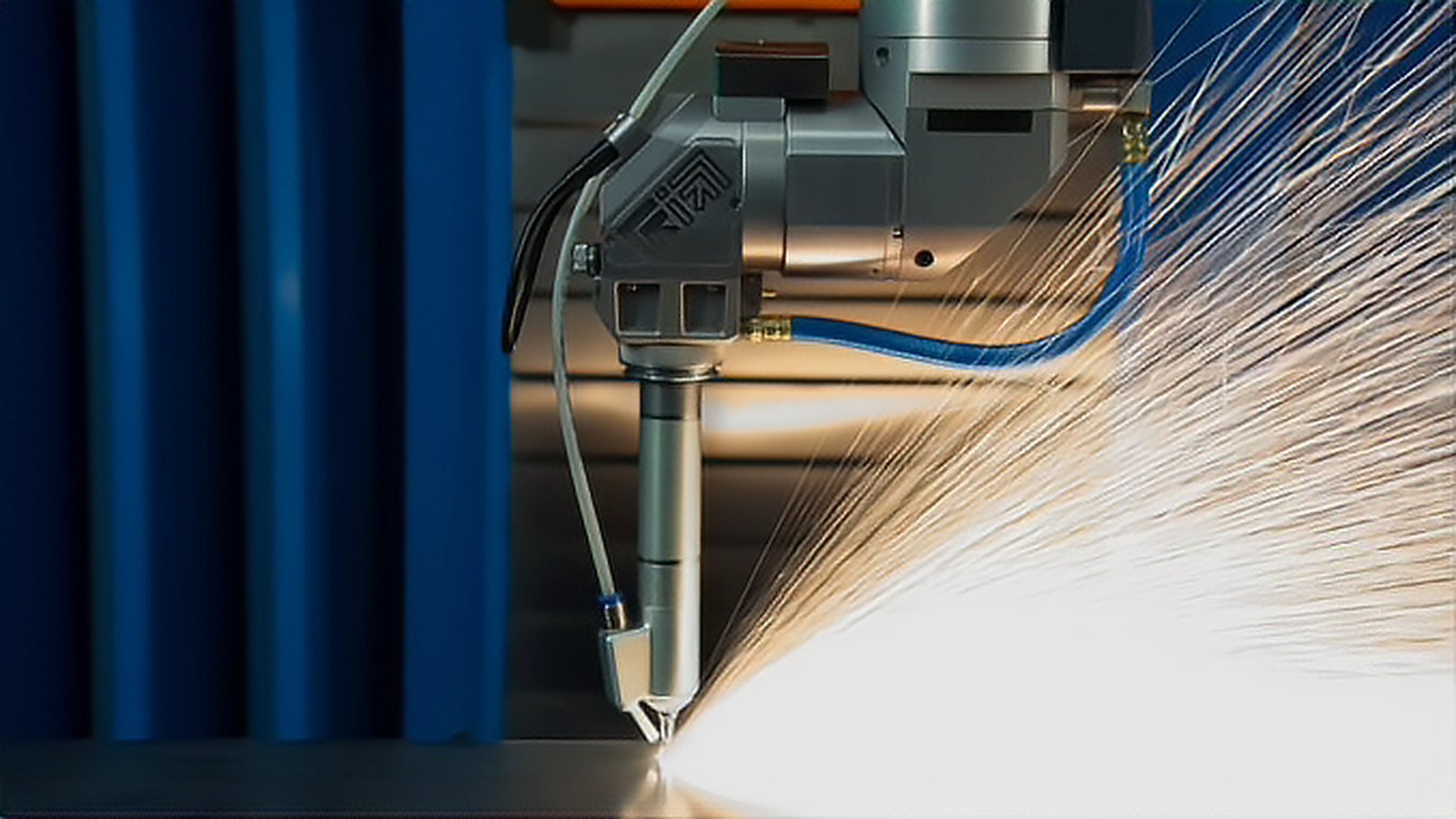
CO2 laser cutting is no longer the default choice for cutting metal, and anyone sizing a robot cell should treat it as a specialized tool rather than a general one. Fiber lasers have taken over most flat sheet metal work for reasons that are physical rather than commercial, and that shift is not going to reverse. This guide explains where CO2 still earns its place, what it costs you in cell design, and how to keep the decision honest when a supplier proposes one.
Why wavelength decides the argument
The two laser families operate at very different wavelengths. A CO2 laser emits at roughly 10.6 micrometres, while a fiber laser emits at roughly 1.06 micrometres, which is 1064 nanometres. That gap drives almost everything downstream, including how well the beam is absorbed, how it is delivered, what assist gas you need, and whether a three dimensional robot cell is even possible.
Absorption is the first consequence. On cold steel, only about 11 percent of CO2 radiation is absorbed, so roughly 89 percent is reflected away. For neodymium YAG radiation the absorbed fraction is closer to 30 percent. Absorption also rises significantly as the material gets hotter, and that is why a cutting front becomes easier to maintain once it is established: the hotter region absorbs more energy, so the process tends to stabilize rather than fade out. That single fact explains a lot of the behaviour operators see on the shop floor, and it is worth understanding before blaming the machine for a cut that will not start.
Efficiency and the mirror problem
CO2 sources are not as inefficient as they are sometimes made out to be. TWI points out that a CO2 laser reaches a wall plug efficiency of around 10 percent, which is higher than most lamp pumped solid state lasers. The comparison that matters today is with fiber sources, which convert electricity into usable beam power two to three times more efficiently at the same rated power, and over the life of a production cell that difference shows up in running cost.
Beam delivery matters even more for a robot cell. CO2 radiation cannot be carried down a flexible fiber, so it has to be steered with mirrors and transmissive optics. This constrains CO2 to two dimensional flat cutting. Short wavelength solid state lasers such as neodymium YAG, and fiber lasers, can be delivered through a fiber, which is exactly what makes three dimensional robot cutting practical. If the part requires an arm to follow a curved seam or a formed panel, that constraint alone often removes CO2 from the shortlist.
Where CO2 genuinely wins
The honest case for CO2 rests on thick metal and on non metals. At equal power, CO2 cuts material thicker than 5 mm faster than a fiber laser and leaves a smoother surface on that thick material. That is a real technical advantage, and it is why CO2 has not disappeared from heavy plate work. If your workload is dominated by thick plate on a flat bed, CO2 is not automatically the wrong answer, which is the substance of the fiber versus CO2 comparison for thick steel.
The picture reverses on thin sheet. Fiber lasers cut thin plate faster because the cutting front absorbs the shorter wavelength more effectively, and at equal power a disc, fiber class laser cuts 0.6 mm and 1.2 mm stainless steel faster with lower edge roughness than CO2 does. The crossover is real, and it is driven by thickness rather than by any brand or model.
CO2 also remains the practical choice for non metals. Wood, acrylic, leather, fabric, paper and plastics are commonly cut with CO2, because fiber lasers handle non metallic materials poorly. Some coated and anodized surfaces are processed with CO2 for the same reason. Treat the non metal case as established shop practice rather than as something a standard requires, because that is what it is. The underlying physics is that these materials absorb the longer wavelength well while bare metals reflect it.
Reflective metals and back reflection
Fiber lasers cut copper, brass and aluminium without the back reflection risk that can damage a machine. Copper, brass and aluminium are also the materials most likely to cause trouble for a CO2 system, so a workload that includes these reflective metals points toward fiber on reliability grounds as well as speed.
Assist gas is a process decision
Gas choice changes what the cut actually is. With oxygen, the material is burned and vaporized, and the exothermic reaction supplies additional energy. That extra energy lets you penetrate thick and reflective material that would otherwise resist the beam. The penalty is that the cut edge carries oxides, which interfere with later welding, promote corrosion, and frequently require expensive post processing to remove.
With an inert gas such as nitrogen or argon, the laser only melts the material and the gas kinetic energy blows the molten metal clear. Because there is no exothermic contribution, the laser power required is usually significantly higher than for oxygen cutting of the same thickness. High pressure nitrogen produces oxide free, burr free edges, but cutting speed has to drop noticeably compared with oxygen. That trade off between edge quality and throughput is one of the most common sources of disagreement between a process engineer and a production planner, so it is better settled before the machine is ordered.
TWI groups laser cutting into three modes. Fusion cutting uses an inert gas to blow molten material clear, with the gas contributing no energy to the process. Flame cutting uses oxygen to create an exothermic reaction that adds energy input. Remote cutting uses such high power density that the material partially vaporizes, so no assist gas is needed at all.
Gas choice also reaches past the cutting cell. If cut edges go straight into a welding fixture, an oxidized edge forces cleaning and can compromise the weld, and oxide left in place promotes corrosion. That is why the gas decision belongs in the process specification rather than in a purchasing line item.
Reactive materials such as titanium need a fully inert atmosphere, which means argon or helium rather than nitrogen. The reasoning is the same in every case: any reactive gas at the cut edge can feed an unwanted reaction, so the gas has to be chosen with the material and not with the machine.
Judging cut quality the right way
Arguments about CO2 versus fiber are only meaningful when measured against a defined yardstick. ISO 9013:2017, Thermal cutting, Classification of thermal cuts, Geometrical product specification and quality tolerances, is that yardstick. The third edition replaced the 2002 version and sits under ISO/TC 44/SC 8. Its scope covers laser cutting from 0.5 mm to 32 mm in thickness.
The standard characterizes a cut face using several features. The perpendicularity and angle tolerance u covers both perpendicularity deviation and flatness deviation. The mean height of the profile, Rz5, describes surface roughness. The standard also addresses dross, top edge melting r, drag and gouging. A cut face is described by a quality level together with a tolerance level, and annexes indicate the quality different cutting processes can realistically achieve.
The specific level designations and tolerance figures sit inside the paid standard and are deliberately not reproduced here. What matters in a specification conversation is that you ask which edition of ISO 9013 a claimed quality class is measured against, and who performed the measurement. In procurement, the standard is useful because it turns a vague request for a good edge into a defined quality level and tolerance level that both sides can reference.
Putting CO2 in a robot cell
Robot integration is where the delivery constraint bites hardest. Because CO2 must be steered with mirrors, the beam path is fixed relative to a flat table, so the machine moves the workpiece or a gantry rather than the beam. That suits flat bed cutting and pallet handling, and it works well in high volume plate shops. It does not suit a six axis arm tracing a three dimensional contour, which is the natural territory of fiber delivered lasers. Matching the source to the motion system is therefore a layout question as much as an optical one, and it should be answered before the floor plan is fixed, as covered in planning a laser robot cell layout.
Cutting also generates fume and particulate, and a robot cell concentrates that generation into a small footprint. With oxygen, and especially on coated or non metallic materials, the fume load is significant enough that extraction has to be a design input rather than a retrofit bolted on after commissioning. The rules of thumb for capture at the source are set out in fume extraction and air quality in laser processing.
Safety follows the same logic. Laser processing at these power levels is subject to laser safety classification and guarding requirements, which means a properly interlocked enclosure and eye protection matched to the wavelength and class in use. The controls are not optional and they are not identical for every wavelength, so they belong in the specification from the start. The practical layout of guarding is covered in laser safety enclosures, eyewear and interlocks.
How to decide
A practical way to settle the choice looks like this.
- If the part is flat, thicker than 5 mm and metallic, CO2 can be competitive on speed and edge finish.
- If the part is thin sheet, fiber is faster and cheaper to run.
- If the material is copper, brass or aluminium, fiber avoids the back reflection problem.
- If the job is three dimensional, you need a fiber delivered source rather than CO2.
- If the material is wood, acrylic, leather, fabric, paper or plastic, CO2 is usually the only realistic choice.
- If the part is both thick and three dimensional, no single source covers it and you have a genuine compromise to make.
The bottom line for robot cells
CO2 laser cutting survives in robot cells in two pockets: heavy metal plate on a flat bed, and non metallic materials. Everywhere else, fiber is the better default for reasons that are technical rather than fashionable. Fiber is more energy efficient, it has no beam path optics to maintain, it carries lower running cost, it handles reflective metals without back reflection damage, and it can be delivered by fiber into three dimensions. A supplier who proposes CO2 for thin sheet, three dimensional or reflective metal work in a robot cell is asking you to accept a constraint you do not actually have. If you are comparing complete cells rather than sources alone, the same trade offs reappear in the automation systems and buyer guide material on this site.
Sources and references
- TWI — Laser Cutting, Cutting Processes - Defines laser cutting fundamentals, including the CO2 wall plug efficiency figure and the comparison with lamp pumped solid state lasers View source
- TWI — Laser Cutting Process Variants - Explains fusion, flame and remote cutting modes and the beam delivery limits that keep CO2 on flat beds View source
- TWI — Cutting Stainless Steel with Disc and CO2 Lasers - Reports that a fiber class disc laser cuts thin stainless faster with lower edge roughness at equal power View source
- BOC LASERLINE technical handbook — Laser cutting - Source for absorption figures on cold steel and for the oxygen versus inert gas assist gas discussion View source
- ISO 9013:2017 — Thermal cutting, Classification of thermal cuts, Geometrical product specification and quality tolerances - The standard used to describe and compare cut face quality, including the terms applied in this article View source
Comments (0)
No comments yet.
Sign in to join the discussion.