Fiber Laser Marking Systems: What to Specify for Industrial Traceability
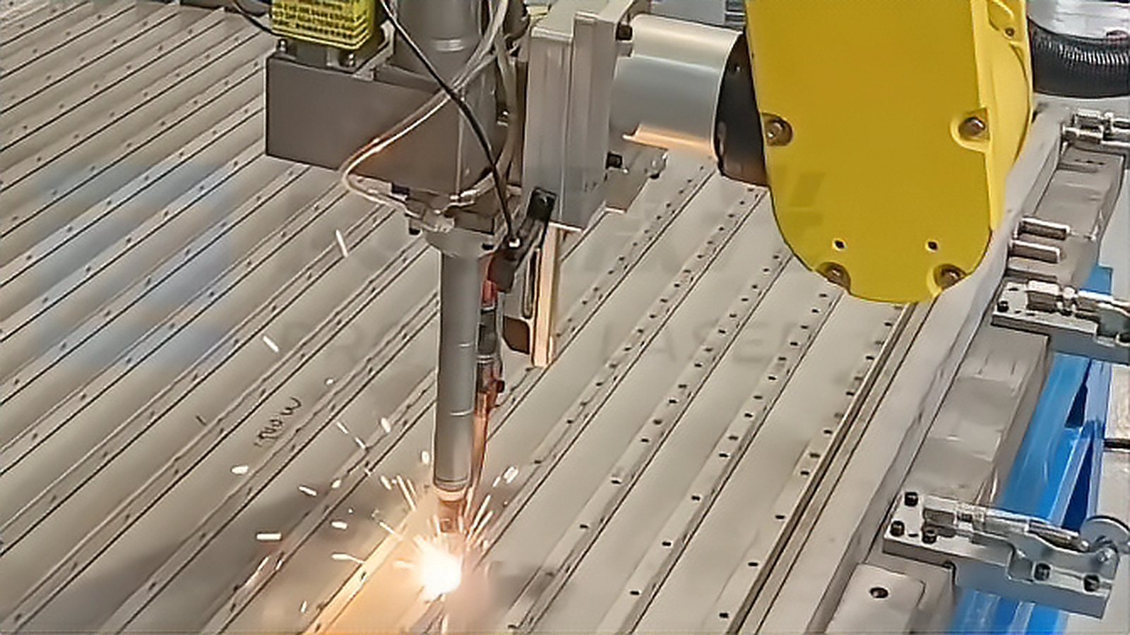
Traceability lives or dies at the point where the mark is made, and a part number that a verifier cannot read at the end of the line is not traceability at all. This article is a specification guide for engineers and procurement teams buying fiber laser marking systems for industrial traceability. It does not rank machines and it makes no claims about which supplier performs better. It sets out what the process does to a surface, how wavelength limits the material, and how quality is measured, so you can write a specification that can be verified rather than argued about.
Marking is not one process
Under the single word marking sit several distinct processes, and they do different things to the part surface. The classification below is the common industry way of describing them rather than a standard definition, but the distinctions are real and they drive both the corrosion behaviour and the traceability of the finished part. The practical comparison of these routes is covered in more detail in laser marking versus laser engraving.
Annealing marking uses the laser to heat the surface so the material oxidizes or undergoes carbon migration. On stainless steel this produces a dark, permanent mark. No material is removed, the surface topography changes very little, the passive layer is largely preserved, and the risk of crevice corrosion and of bacteria hiding in the mark is low.
Engraving removes material to form a clear groove. Inside that groove the passive layer is destroyed, which raises the crevice corrosion risk.
Etching produces shallow melting or ablation and slightly roughens the surface.
The substance of the comparison between these processes comes down to three questions: whether material is removed, whether the passive layer is broken, and how much the surface topography changes. The difference between oxidation marking, annealing marking and engraving all follows from those three points, so it is worth stating them explicitly in any requirement document.
For stainless steel parts that see moisture, chloride exposure or hygienic cleaning, the choice between annealing and engraving is not a matter of taste. An engraved mark removes material and destroys the passive layer inside the groove, which is exactly where crevice corrosion begins. An annealing mark leaves the surface largely intact, which is why it is the more conservative choice where corrosion resistance and cleanability matter.
Wavelength determines what you can mark
The laser wavelength sets which materials can be marked at all, and no amount of power will fix the wrong choice. A fiber laser emits at roughly 1064 nanometres and couples well to steel, stainless steel, aluminium, brass and titanium, which allows high energy density clean ablation on those metals.
A CO2 laser emits at roughly 10.6 micrometres and is poorly absorbed by bare metal. Marking bare metal with CO2 usually requires a marking agent or coating, or else it is limited to coated and anodized surfaces.
An ultraviolet laser at 355 nanometres performs cold marking. It breaks molecular bonds and produces almost no heat, which suits sensitive electronics, glass and plastics.
A blue diode laser operates at around 450 nanometres.
These material fit rules are industry practice rather than a standard. Even so they are the first thing to settle, because the wrong wavelength turns a solvable marking problem into an unsolvable one. It is also worth remembering that the rules concern coupling, not power. A CO2 system run at high power still struggles with bare metal because the surface reflects most of the beam rather than absorbing it, while a fiber source couples efficiently into the same part. When a marking problem resists every parameter change, the first question to ask is whether the wavelength suits the material and not whether the power is high enough.
What traceability actually requires
A part is only traceable when its mark is machine readable at a defined quality, not merely visible. The reference method for two dimensional symbol print quality is ISO/IEC 15415:2024, Information technology, Automatic identification and data capture techniques, Bar code symbol print quality test specification, Two-dimensional symbols. The third edition is the current version. It grades a symbol from 4.0 down to 0.0, corresponding to A through F, and the overall grade is the lowest of all the evaluated parameters. That last point is the one that catches people out: a code that is excellent in every respect except one parameter still takes the failing parameter grade.
ISO/IEC 16022 is the Data Matrix symbol specification, so it defines the symbol itself rather than the measurement of its quality. Both matter, but they answer different questions. If you are new to the traceability requirement itself, the industry applications material on this site shows how marking requirements appear across sectors, while the buyer guides collection covers how to turn them into a purchase specification.
Direct part marking is not graded the same way as printing on paper. A mark made on a metal surface needs dedicated lighting conditions and a supplementary set of parameters, including cell contrast, cell modulation and fixed pattern damage. It is assessed against a dedicated direct part marking quality guideline rather than the paper based method. If a supplier hands you a grading result, check whether it was produced under those direct part marking conditions or by simply pointing a paper code verifier at a metal part. The two are not interchangeable.
The overall grade taking the lowest parameter value is what makes the method useful for traceability. It prevents a code with strong contrast but a damaged finder pattern from being reported as good, because a verifier that cannot locate the symbol cannot read it. For a marking specification, that means you should not accept an averaged or partial result; ask for the full set of evaluated parameters and the resulting overall grade.
Peer reviewed work uses this grading approach directly. A study titled Influence of laser marking parameters on data matrix code quality evaluated codes using the two dimensional symbol quality method. That is the model to follow when you build your own acceptance test, because it ties a process parameter to a measurable grade rather than to an impression.
Parameters move you along the process spectrum
Marking quality is set by the combination of laser power density, pulse frequency, pulse width, scan speed, defocus and overlap. Those parameters change the heat input into the surface, and heat input is what decides whether you land in annealing marking or in engraving. That is not a cosmetic distinction. It changes whether the passive layer survives and it changes the readability grade of the code you just wrote.
This is why two systems that look identical on a data sheet can produce marks with different grades. A parameter set that produces a pleasing dark mark at one focus offset can produce a shallow, low contrast mark that fails verification at another. Nothing about the machine changed; the recipe did.
For any part where traceability matters, the acceptance method is to measure the grade using the two dimensional symbol quality method, not to judge by eye that the mark looks clear. Clear to a human and compliant to a verifier are different tests, and only the second one protects you in an audit.
None of this is visible on a purchase order, which is why the parameter set cannot be treated as a factory setting handed over with the machine. It is part of the process qualification for each part number, and it has to be re-verified whenever the fixture, the surface finish or the incoming material changes.
Specifying a system
Work through the decisions in this order, because each one constrains the next.
- Choose the wavelength for the material first: fiber for steel, stainless steel, aluminium, brass and titanium; CO2 only where you are working with coated or anodized surfaces or using a marking agent; ultraviolet for glass, plastics and sensitive electronics; blue diode where it fits the material.
- Choose the marking type deliberately: annealing marking where the passive layer and corrosion resistance must survive, engraving where a deep durable mark matters more than surface integrity, etching where a light shallow change is enough.
- Define the symbol and the grade before you buy: Data Matrix is specified by ISO/IEC 16022 and graded under ISO/IEC 15415:2024, so state which symbol you need and which grade it must reach.
- Require direct part marking grade conditions: on metal parts the measurement needs dedicated lighting and the direct part marking parameter set, not a paper based verifier.
- Lock the recipe to the part: power density, pulse frequency, pulse width, scan speed, defocus and overlap should be recorded as a verified recipe per part number, not left to whichever operator is on shift.
Safety and integration
Laser marking is laser processing, and it remains subject to laser safety classification and guarding requirements. That means an enclosure, interlocks and eye protection matched to the wavelength and class in use, and it means treating a marking station with the same seriousness as a cutting or welding cell. The requirements that carry over from welding cells are set out in this article on laser safety enclosures, eyewear and interlocks.
Marking can also release fume and particulate, particularly on metals and coatings, so extraction at the source belongs in the layout rather than in a later improvement project. The capture principles are the same as for other laser processes, described in fume extraction and air quality in laser processing.
The specification summary
Buy the wavelength for the material, choose the marking type for the surface requirement, define the symbol and the target grade before purchase, require verification under direct part marking conditions on the real part, and lock a verified parameter recipe to each part number. Everything else, including a machine headline power rating, is secondary to those decisions.
Sources and references
- JPT Laser — Laser annealing marking - Industry technical page describing annealing marking, engraving and etching and their effects on the passive layer View source
- HBS Lasers — How laser marking machine works - Industry source for how wavelength governs which materials a marking laser can process View source
- Laser Mark Tech — Laser engraver for metals - Industry source used for the wavelength and material fit discussion View source
- ISO/IEC 15415:2024 — Information technology, Automatic identification and data capture techniques, Bar code symbol print quality test specification, Two-dimensional symbols - Defines the two dimensional symbol grading method and grading scale used for traceability marks View source
- Influence of laser marking parameters on data matrix code quality - Peer reviewed study applying the two dimensional symbol quality method to laser marked codes View source
Comments (0)
No comments yet.
Sign in to join the discussion.