Real Time Weld Quality Monitoring: Sensors and Data
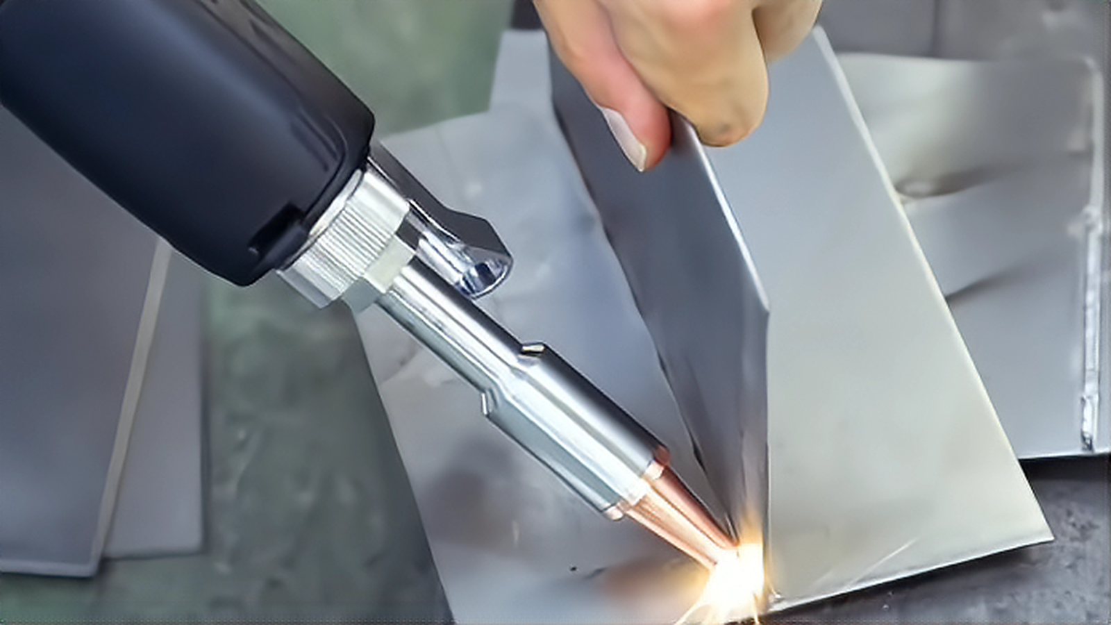
Laser weld monitoring turns a welding cell into a source of measurement, and the value of that measurement depends on which signals are collected and what is done with them. Coaxial photodiodes, optical coherence tomography heads and cameras each answer a different question, and none of them replaces a cross section. This article explains what each sensor actually measures, how to set thresholds that carry meaning, and how to keep a traceable record per part without drowning the plant in data.
What a Coaxial Sensor Sees
A coaxial monitoring head splits light collected through the same optics that deliver the beam, so it observes the process from the direction of the keyhole rather than from the side. Photodiodes behind dichroic mirrors separate that light into bands. The shorter wavelengths carry plasma and process emission, which rises with intensity and instability, while the longer wavelengths carry thermal radiation from the melt pool, which tracks its size and temperature. A third channel often measures back reflected light, which is especially informative when welding copper or aluminum because a sudden change in reflection signals that the keyhole has formed or collapsed. Because the view is coaxial, the signal is largely independent of the seam direction and of part geometry, which is why this arrangement is the default in production cells.
Optical Coherence Tomography and Keyhole Depth
Optical coherence tomography measures distance by interferometry and, when integrated coaxially, reports the depth of the keyhole in real time. That is a different class of information from emission intensity, because depth is a geometric quantity that correlates directly with penetration. The technology is used to confirm that penetration stays inside a window, to detect the transition to full penetration in a lap joint, and to act as the feedback signal in a closed loop controller that trims power. Vendors commonly quote depth accuracy in the tens of micrometers and sampling rates in the kilohertz range, but those numbers describe typical claims rather than results you can assume on your own material, and the actual useful resolution depends on the surface condition and the stability of the keyhole. The method also fails to see anything once the beam has fully penetrated a thin sheet, so it is most useful in partial penetration work.
Cameras and Position Feedback
A camera placed off axis can watch the top bead, the spatter and the seam position, which no coaxial photodiode can do. Its weakness is parallax and occlusion by the torch, so it needs a clear line of sight and a lighting strategy that survives the process glow. In laser cells the camera is often the seam tracking device rather than the quality monitor, providing the correction that keeps the beam centered in the joint. Where both functions are needed, many integrators run a camera for tracking and a coaxial sensor for quality, then merge the two data streams at the cell controller.
Setting Thresholds That Earn Their Keep
A monitoring system is only as good as its limits. The practical method is to weld a set of coupons that deliberately includes good joints and known defects, section every one of them, and then align the recorded signals with what the metallography shows. This produces an envelope with an upper and lower boundary, and the alarm logic is built on departures from that envelope rather than on absolute values, because signal level drifts with optics contamination, lens protection glass condition and material batch. Expect false alarms and budget for them. A system that flags a few percent of good parts for review is tolerable if the escape rate of bad parts falls to near zero, but a system that flags a quarter of production will be switched off within a month.
Data, Traceability and Retention
A welding cell sampling several channels at kilohertz rates produces a large volume of data, and storing all of it raw per part is rarely practical for a full shift. The common compromise is to extract features at the edge, keeping minimum, maximum, mean and spread over windows of the seam and storing the raw trace only when an alarm occurs. The record is then linked to a part serial number read from a data matrix code or a fixture position, which allows any unit in the field to be traced back to its welding data. Automakers and medical device manufacturers are the main drivers of this practice, and it also pays off internally during a process investigation. Whatever the retention period, it should be stated in the control plan, because data that is deleted after a week answers no questions about a warranty claim.
Monitoring does not remove the need for verification. Quality levels for laser beam welds are defined in standards such as ISO 13919 part 1 for steel and ISO 13919 part 2 for aluminum, and destructive or non destructive testing remains the reference method. Treat monitoring as a high rate screen that directs attention, keep the cross section as the arbiter, and start with one signal that you can interpret rather than five that you cannot.
Comments (0)
No comments yet.
Sign in to join the discussion.