Joining Steel to Aluminum: Controlling Brittle Intermetallics
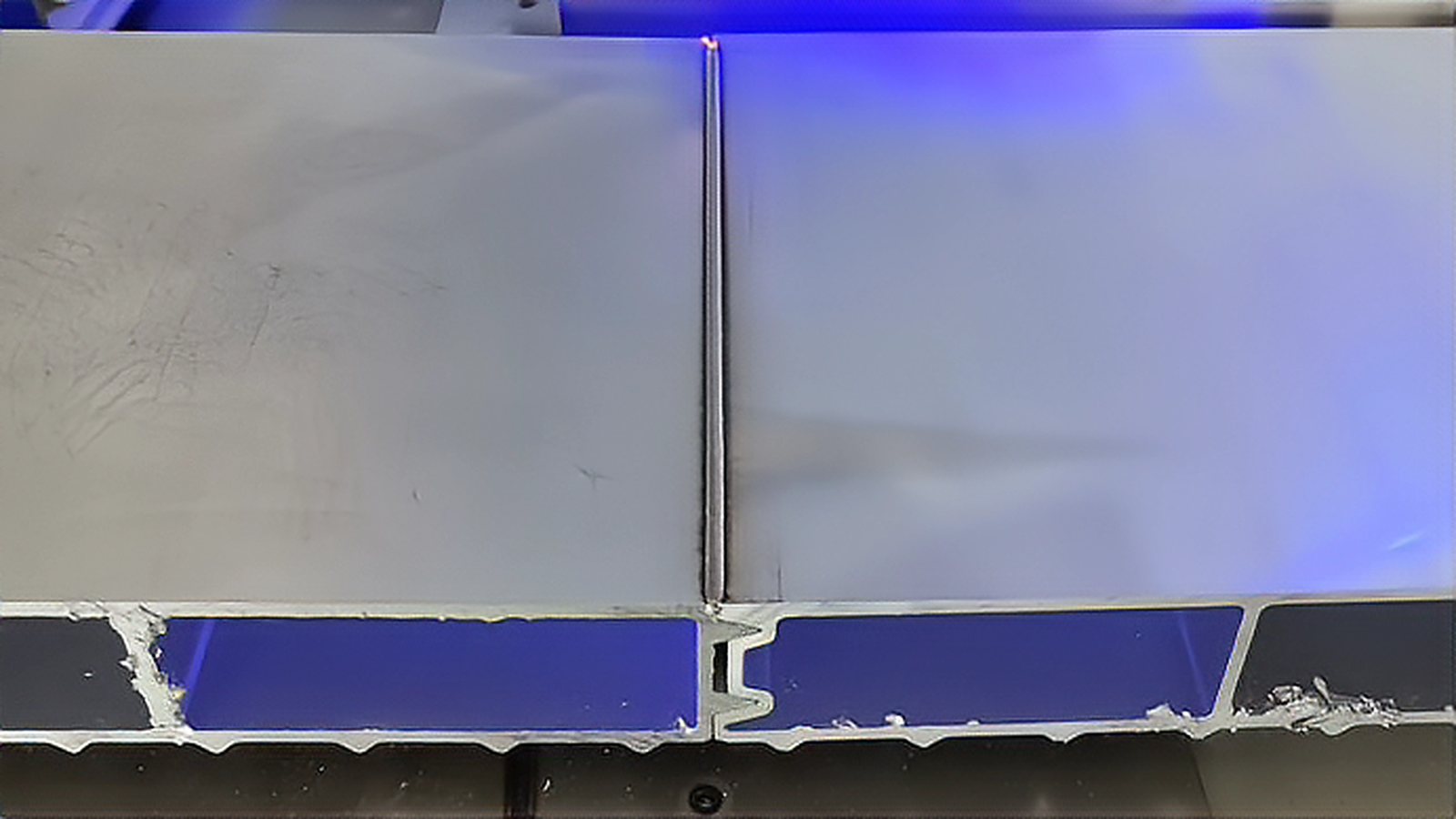
Dissimilar metal laser welding between steel and aluminum fails for one reason: the two metals react at the interface and form hard, brittle intermetallic compounds, and the joint then cracks along that thin layer. The compounds that matter most are Fe2Al5, which grows as tongue shaped crystals into the aluminum side, and FeAl3, which forms closer to the aluminum. Both are far harder than either parent metal. This article explains how the reaction layer grows, which process levers keep it thin, and how to design and inspect a joint that survives service.
What Goes Wrong at the Interface
Iron and aluminum are not soluble in each other in the solid state, so any joint relies on a thin reaction zone rather than on mixing. That zone is a ceramic like layer with a hardness commonly reported near 1000 HV, while the aluminum around it sits at roughly 35 HV and mild steel near 150 HV. Because the layer is thin and hard, strain concentrates in it, and a joint that looks sound after welding can fail in a bend test or after thermal cycling. Welding literature usually cites a critical thickness of about 10 micrometers, above which the joint becomes prone to brittle fracture. Layer growth is diffusion controlled, so what actually governs the outcome is not peak temperature alone but the time the interface spends hot.
Heat Input, Filler and Beam Position
The first response to a cracking problem is to shorten the thermal cycle. Higher travel speed with matched power reduces the time available for diffusion and is the single most effective control; speeds in the range of several meters per minute are common when welding thin sheet, and slower welds almost always produce a thicker reaction layer. Defocusing the beam spreads energy and lowers peak intensity, which helps if the travel speed is already at the limit of the motion system. Reducing total heat input also limits distortion, which matters because the two metals expand at different rates and a warped part opens the gap that the process was tuned to close.
The second lever is the alloy that ends up at the interface. Aluminum silicon filler, typically 4043 or 4047, dilutes the reaction and produces a thinner, more forgiving layer than a pure aluminum melt does. The third lever is beam position. Offsetting the focus toward the aluminum side keeps the steel below its melting point, so only the aluminum and the filler melt and the steel is merely wetted. This is the principle behind laser brazing of steel to aluminum, and it works because a solid steel surface reacts far more slowly than a molten one. Wetting is the practical difficulty: the steel surface must be clean and the shielding gas must cover the pool well, otherwise the filler balls up instead of flowing along the joint.
Design Around the Weak Interface
Because the interface remains the weak link, the joint geometry should never put it in peel. Overlap joints loaded in shear perform far better than butt joints loaded in tension, and adding a mechanical element such as a rivet, a clinch or a bonded flange lets the structure carry the load while the laser weld provides conductivity, sealing and stiffness. Adhesive bonding is a common companion process, since the adhesive spreads load away from the reaction layer and also seals the gap against moisture. Aluminum silicon coated press hardened steel, used in hot stamped structural parts, welds to aluminum more predictably than bare or zinc coated steel because the surface already presents an aluminum rich layer to the pool.
Interlayers and Coatings
Another route is to insert a metal that reacts less aggressively with both sides. Nickel, copper and zinc interlayers have all been studied for steel to aluminum joints, and zinc coatings in particular change the interface chemistry in ways that reduce the brittle iron aluminum phases. These approaches are promising but sensitive to coating weight, thickness control and process repeatability, so they should be treated as development work until a specific stack and a specific recipe have been validated with metallography. The same caution applies to any claim that a coating removes the problem entirely; it usually redirects the reaction rather than eliminating it.
Measuring and Validating the Joint
A steel to aluminum joint cannot be qualified by appearance. The working method is to cut cross sections, measure the reaction layer at several points along the seam, and record the maximum rather than the average, because one thick band is enough to start a crack. A microhardness traverse across the interface confirms the phase distribution, a bend or peel test exposes brittleness that a tensile test can miss, and resistance measurements matter for battery and busbar applications where the joint is also an electrical conductor. Corrosion deserves the same attention: aluminum is anodic to steel, so water trapped in an open overlap will attack the aluminum, which is a strong argument for sealing the joint edge with adhesive or a coating.
Pick one production joint and characterize it completely before writing a specification. Fix the filler alloy, the offset and the shielding gas, then raise travel speed until the reaction layer is thin and consistent, and confirm the result with cross sections from parts made at the start and end of a shift. If the layer cannot be held below the limit in production, change the joint design and carry the load with a mechanical element rather than chasing a weld that the metallurgy will not allow.
Comments (0)
No comments yet.
Sign in to join the discussion.