Burn-Through in Laser Welding: Causes and Prevention on Thin Sheet
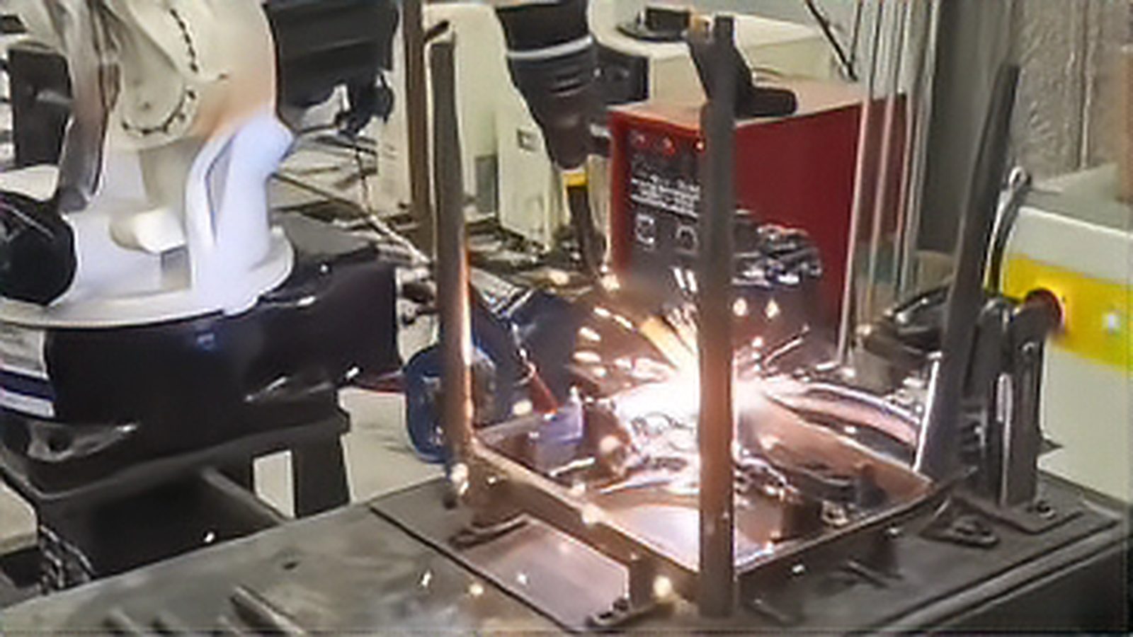
Burn-through on thin sheet is not gradual. A few percent more power or a slightly slower traverse can turn a sound weld into a hole. This article explains why the fault behaves like a threshold rather than a slope, how heat builds along a seam, where the acceptance limits come from in ISO 13919-1, and which levers widen the window.
What burn-through actually looks like
Burn-through is not a single defect. At the mild end the root sags below the parent metal, further along the pool collapses into an open hole, and in the worst case the local section drops out. Burn-through and lack of fusion sit at opposite ends of one window, between a power floor that fails to penetrate and a ceiling that punches through, so start with a structured view of welding defects before you tune.
Where the acceptance limits come from
Before you adjust a single value, decide what a good weld is. ISO 13919-1:2019 sets quality levels for imperfections in laser and electron beam welds in steel, nickel, titanium and their alloys, and defines three levels, B, C and D, for material 0.5 mm and thicker. It sets the severity of imperfections but not how to inspect them, since technique and acceptance levels come from separate documents. For aerospace work, AWS D17.1/D17.1M:2024 governs fusion welding and is firmer on procedure and operator qualification, so confirm which system your drawing invokes.
Why thin sheet behaves like a threshold
Thin sheet is unforgiving for a simple geometric reason. Once the keyhole has passed through the full thickness there is no material left below it to absorb surplus energy, so the pool has nothing to hold onto. The response curve is steep near the limit rather than gentle, so you cannot find the window edge by large jumps. Move power in steps of about five percent and speed likewise, and note where the weld first becomes unstable.
Heat accumulation on corners and short seams
Parameters that run perfectly down a long straight seam can burn through on a short corner, and the difference is time. Corners, tack-to-tack runs, frequent starts and stops, and overlapping path sections concentrate heat faster than the sheet can conduct away. This is why cell layout and motion planning belong before a welding program is locked.
Focus position and power density
Defocus is a blunt but useful tool on thin sheet. Moving the focal point away from the surface spreads the energy over a larger spot and lowers peak power density, raising the threshold at which material is lost. Negative and positive defocus behave differently on thin sections because the beam geometry inside the metal differs, so trial both. An oversized spot at very low travel speed can still collapse once heat soaks through, and focus is not a substitute for power control, but it is often the cheapest margin, as the guide to laser welding parameters explains.
Gap, fit-up and backing
In production, gaps and mismatch cause more burn-through than any parameter error. A gap reduces the section carrying the load and lets the pool drop through, while mismatch moves the seam off the joint line so the beam spends its energy on one sheet. TWI's study of laser welding automotive steel and aluminium notes that for thin butt joints the gap has to be held to a small fraction of the material thickness, on the order of ten to fifteen percent. A backing bar or backing gas helps, but neither rescues a badly fitted joint.
Ramps, start points and path strategy
Because the failure is driven by time, shaping heat input over time matters as much as setting its level. Ramp power up and down at the start and end of each seam instead of switching it on at full value, and start in a scrap tab or a process hole so the transient never lands on a finished surface. Manage overlap on closed paths and let the part cool between runs.
Qualifying the procedure before production
Once you have a window, lock it into a written procedure. ISO 15609-4:2009 specifies what a laser beam welding procedure specification has to state, and ISO 15614-11:2025 describes how such a procedure is qualified by test. They matter on thin sheet because they force you to record the variables that shift the threshold, such as power, speed, focus and gas, and to define a range of approval around the tested values. ISO 18491:2026 addresses the measurement of arc energies; it is written for arc processes, so treat it as an analogy for how heat input is quantified, not as a laser rule.
When a different joint is the real answer
If the window stays narrow after all of the above, the geometry may be the problem rather than the process. Converting a butt to a lap or flange joint gives the pool something to sit on and widens tolerance to gap and power. Filler wire, cold or hot, increases the metal available to bridge and fill, at the cost of extra hardware. Where short, awkward seams dominate the cycle, a pulsed mode may be the sensible choice, as the comparison of laser welding and MIG sets out.
Catching burn-through before it becomes scrap
No process window survives production long without some monitoring. Melt-pool observation and through-the-lens viewing can flag the moment the pool changes shape, and simple interlocks can stop the cycle when the signal leaves a defined band, as the material on real-time weld quality monitoring notes. Decide how you will judge a suspect part, what repair is permitted, and how many repairs it can take, and set the acceptance limit from the drawing rather than at the machine.
The first principle on thin sheet is to control how heat is distributed in time, not simply how much power is dialled in. Before changing a number, ask where the part is hottest and for how long, then shorten that moment or let the part cool.
Sources and references
- ISO 13919-1:2019 Electron and laser-beam welded joints - Quality levels for imperfections - Part 1: Steel, nickel, titanium and their alloys - Defines the B, C and D quality levels used to judge burn-through and other imperfections in laser welds View source
- ISO 15614-11:2025 Specification and qualification of welding procedures - Welding procedure test - Part 11: Electron and laser beam welding - Describes how a laser welding procedure is qualified by test before production View source
- ISO 15609-4:2009 Specification and qualification of welding procedures - Welding procedure specification - Part 4: Laser beam welding - Lists the variables that a laser beam welding procedure specification must record View source
- AWS D17.1/D17.1M:2024 Specification for Fusion Welding for Aerospace Applications - Sets aerospace fusion welding requirements, including procedure and operator qualification View source
- TWI, Materials Processing with a 10kW Nd:YAG Laser Facility, 1999 - Reports full-penetration welding of 12 mm and 15 mm carbon-manganese steel, a maximum penetration of about 18 mm, and joints assessed to EN-ISO 13919-1 level B View source
- ISO 18491:2026 Welding and allied processes - Measurement of arc energies - Provides a method for quantifying heat input in arc welding, cited here only as an analogy for laser welding View source
Comments (0)
No comments yet.
Sign in to join the discussion.